Logictools
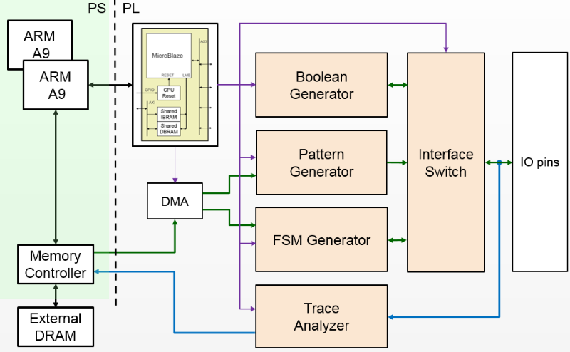
The logictools subpackage contains drivers for the Trace Analyzer, and the three PYNQ hardware generators: Boolean Generator, FSM Generator, and Pattern Generator.
Block Diagram
States
The basic operation of the main hardware blocks in the logictools overlay is the
same. A set of methods which is common to all blocks is used to control basic
operations, setup(), run(), step(), stop(), reset(). The
operation of these methods will be described later.
Each block may have additional unique methods to provide functionality specific to that block.
The state diagram for the blocks is shown below:
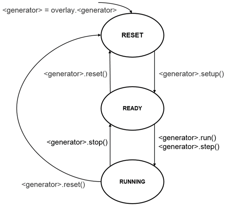
Any one of these hardware blocks, or any combination can be configured and run synchronously following the state diagram above.
RESET
This is the state a block will start in after the overlay is loaded. A block
will remain in the reset state until it has been configured using the
setup() method. It will return to this state if reset() is called.
In the reset state, all IO accessible to the logictools overlay are disconnected from the main logictools hardware blocks. This prevents the inadvertent driving of any external circuitry that is connected to the board. This is done by configuring the interface switch to disconnect all IO from the internal hardware.
The Pattern Generator contains BRAM to store the pattern to be generated. The BRAM is configured with zeros in this state.
Similarly, the FSM Generator configuration is stored in a BRAM which is also configured with zeros in this state.
READY
In this state, the generators / analyzer have been configured. The input and output pins that will be connected have been specified, and reserved, but the interface switch has not bee configured to connect these pins to the internal hardware.
RUNNING
Once the generators are in the ready state, calling run() or step() will move them to the READY state. When moving to this state, the interface switch is configured to connect external IO. The hardware block(s) will start operating in this state.
Running will start the block running in single-shot mode by default. In this mode, the generator will run until enough number of samples are captured by the trace analyzer, or the pattern has completed; then the generator and analyzer both go back to the READY state.
Boolean Generator always runs in continuous mode as a special case.
In continuous mode, the Pattern Generator generates its pattern continuously, looping back to the start when it reaches the end of the pattern. The FSM Generator will continue to run until it is stopped.
Methods
Each generator / analyzer has the following methods:
setup()- configure the block and prepare Interface Switch configurationrun()- connect IO and start the block runningstop()- disconnect IO and stop the block runningstep()- run a single step for the pattern or FSM generatorreset()- clear the block configurationtrace()- enable/disable trace
setup()
Each block must be configured using the setup() method before it can be
used. This defines a configuration for the block, and the configuration for the
Interface Switch to connect the external IO. Note that the configuration is
defined, but the IO are not connected during setup.
run()
The run() method will move a block to the RUNNING state and the block will
start operating. The specified number of samples will be captured by the Trace
Analyzer.
step()
The step() method is similar to run(), but instead of running, all the
generators are single stepped (advanced one clock cycle) each time the step
method is called.
When stepping the Pattern Generator, it will step until the end of the configured pattern. It will not loop back to the beginning.
The FSM Generator can be single stepped until a enough samples are captured by the Trace Analyzer.
stop()
If a block is running, it must be stopped before re-running.
Once a block is stopped, its outputs are disconnected from the external IO, and will only be reconnected when the block is set to run again.
trace()
Trace is enabled by default for each block. When trace is enabled, the Trace
Analyzer will capture trace data for all connected blocks. The trace()
method can be used to enable/disable the Trace Analyzer for each block.
reset()
This method resets the generator to its initial state. This method needs to be called before changing the configuration for a hardware block.
Boolean Generator
The Boolean Generator supports up to Boolean functions of up to five inputs on each output pin. AND, OR, NOT, and XOR operators are supported.
Block Diagram
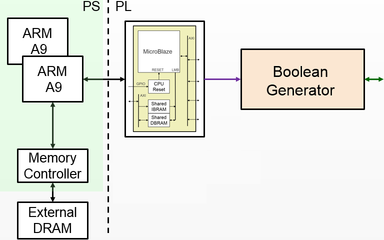
On the PYNQ-Z1 the 20 digital pins of the Arduino shield interface (D0 - D19) can be used as inputs or outputs. The 4 pushbuttons (PB0 - PB3) can be used as additional inputs, and the 4 user LEDs (LD0 - LD3) can be used as additional outputs. This gives a maximum of 24 inputs and outputs available to the Boolean Generator, supporting up to 24 Boolean functions.
Boolean functions are specified, as strings.
For example the following specifies that the values of pushbuttons 1 and 0 are XORed to produce the value on LED0:
'LD0 = PB0 ^ PB1'
Combinatorial Boolean expressions can be defined in a Python list using the expressions & (AND), | (OR), ! (NOT), ^ (XOR).
The expression defines if a pin is used as an input or output.
Examples
The following list defines four combinatorial functions on pins D8-11, which are built using combinatorial functions made up of inputs from pins D0-D3. Any pin assigned a value is an output, and any pin used as a parameter in the expression is an input. If a pin is defined as an output, it cannot be used as an input.
from pynq.overlays.logictools import LogicToolsOverlay

logictools = LogicToolsOverlay('logictools.bit')
boolean_generator = logictools.boolean_generator

function_specs = ['D3 = D0 ^ D1 ^ D2']
function_specs.append('D6 = D4 & D5')
The function configurations can also be labelled:
function_specs = {'f1': 'D3 = D0 ^ D1 ^ D2',
                  'f2': 'D6 = D4 & D5'}
Once the expressions have been defined, they can be passed to the BooleanGenerator function.
boolean_generator.setup(function_specs)
boolean_generator.run()
To disconnect the IO pins, stop it.
boolean_generator.stop()
If users want to use a different configuration, before calling setup()
again, users have to call reset(); this will clear all the reservations on
the currently used pins.
boolean_generator.reset()
More information about the Boolean Generator module and its API can be found in the pynq.lib.logictools Package section.
For more examples see the Logictools Notebooks folder on the Pynq-Z1 board in the following directory:
<Jupyter Home>/logictools/
Pattern Generator
The Pattern Generator allows arbitrary digital patterns to be streamed to IO. This can be used to test or control external circuits or devices.
Block Diagram
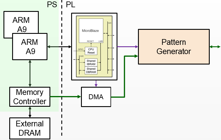
The Pattern Generator supports up to 64K pattern words. Though the memory is 32-bits wide, only least significant 20 bits are used which are routed to the Arduino pins. A data word is generated once every rising edge of the sample clock.
The sample clock is programmable. The minimum sample clock speed is 252 KHz, and the maximum speed is 10 MHz.
The Pattern Generator class is instantiated by importing it from the logictools sub-package.
Examples
from pynq.overlays.logictools import LogicToolsOverlay

logictools = LogicToolsOverlay('logictools.bit')

pattern_generator = logictools.pattern_generator
More information about the Pattern Generator module and its API can be found in the pynq.lib.logictools Package section.
For more examples see the Logictools Notebooks folder on the Pynq-Z1 board in the following directory:
<Jupyter Home>/logictools/
FSM Generator
The Finite State Machine (FSM) Generator can generate a finite state machine in programmable hardware from a Python description.
Block Diagram
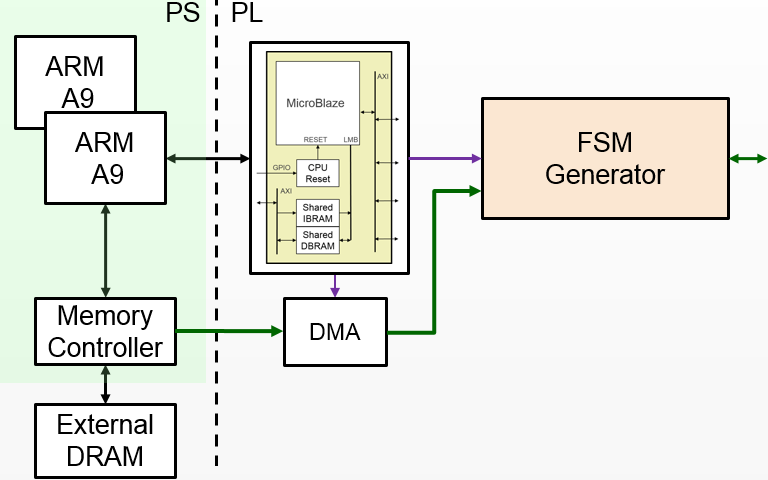
The FSM generator has an internal Block Memory which implements the finite state machine. The 20 pins on the Arduino shield header are available. The FSM must have a minimum of 1 input, allowing a maximum of 19 outputs. The maximum number of inputs is 8. For example, based on the number of inputs, the following configurations are available:
| # Inputs | Max # States | Max # Outputs |
|---|---|---|
| 8 | 31 | 12 |
| 7 | 63 | 13 |
| 6 | 127 | 14 |
| 5 | 255 | 15 |
| 4 | 511 | 16 |
The Trace Analyzer is controlled by a MicroBlaze subsystem. It is connected to a DMA, also controlled by the MicroBlaze subsystem which is used to load configuration information, including the Block Memory configuration to implement the FSM.
The configuration for the FSM, Input pins, output pins, internal states, and state transitions, can be specified in a text format.
Examples
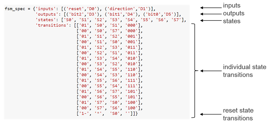
The FSM specification is passed to the setup(). The run() method can
then be used to start the FSM.
The FSM Generator can be used in a similar way to the other generators.
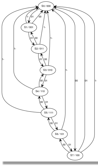
Two additional methods are available to show the FSM state diagram in a notebook, and to display the waveform from the FSM.
show_state_diagram()
show_waveform()
Example of a state diagram:
More information about the FSM Generator module and its API can be found in the pynq.lib.logictools Package section.
For more examples see the Logictools Notebooks folder on the Pynq-Z1 board in the following directory:
<Jupyter Home>/logictools/
Trace Analyzer
Traditional on-chip debug allows FPGA resources to be used to monitor internal or external signals in a design for debug. The debug circuitry taps into signals in a design under test, and saves the signal data as the system is operating. The debug data is saved to on-chip memory, and can be read out later for offline debug and analysis. One of the limitations of traditional on-chip debug is that amount of local memory usually available on chip is relatively small. This means only a limited amount of debug data can be captured (typically a few Kilobytes).
The on-chip debug concept has been extended to allow trace debug data to be saved to DDR memory. This allows more debug data to be captured. The data can then be analyzed using Python.
The trace analyzer monitors the external PL Input/Output Blocks (IOBs) on the PMOD and Arduino interfaces. The IOBs are tri-state. This means three internal signals are associated with each pin; an input (I), and output (O) and a tri-state signal (T). The Tri-state signal controls whether the pin is being used as a input or output. The trace analyzer is connected to all 3 signals for each IOP (PMOD and Arduino).
Block Diagram
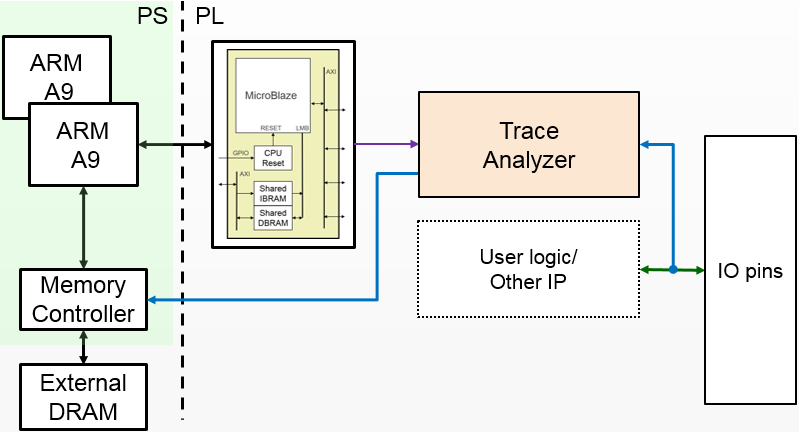
This allows the trace analyzer to read the tri-state, determine if the IOB is in input, or output mode, and read the appropriate trace data.
Examples
More information about the Trace Analyzer module and its API can be found in the pynq.lib.logictools Package section.
For more examples see the Logictools Notebooks folder on the Pynq-Z1 board in the following directory:
<Jupyter Home>/logictools/