Pmod
The Pmod subpackage is a collection of drivers for controlling peripherals attached to a Pmod port.
A Pmod port is an open 12-pin interface that is supported by a range of Pmod peripherals from Digilent and third party manufacturers. Typical Pmod peripherals include sensors (voltage, light, temperature), communication interfaces (Ethernet, serial, WiFi, Bluetooth), and input and output interfaces (buttons, switches, LEDs).
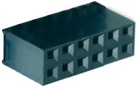
Each Pmod connector has 12 pins arranged in 2 rows of 6 pins. Each row has 3.3V (VCC), ground (GND) and 4 data pins. Using both rows gives 8 data pins in total.
Pmods come in different configurations depending on the number of data pins required. E.g. Full single row: 1x6 pins; full double row: 2x6 pins; and partially populated: 2x4 pins.

Pmods that use both rows (e.g. 2x4 pins, 2x6 pins), should usually be aligned to the left of the connector (to align with VCC and GND).

Pmod peripherals with only a single row of pins can be connected to either the top row or the bottom row of a Pmod port (again, aligned to VCC/GND). If you are using an existing driver/overlay, you will need to check which pins/rows are supported for a given overlay, as not all options may be implemented. e.g. the Pmod ALS is currently only supported on the top row of a Pmod port, not the bottom row.
All pins operate at 3.3V. Due to different pull-up/pull-down I/O requirements for different peripherals (e.g. IIC requires pull-up, and SPI requires pull-down) the Pmod data pins have different IO standards.
Pins 0,1 and 4,5 are connected to pins with pull-down resistors. This can support the SPI interface, and most peripherals. Pins 2,3 and 6,7 are connected to pins with pull-up resistors. This can support the IIC interface.
Pmods already take this pull up/down convention into account in their pin layout, so no special attention is required when using Pmods.
Block Diagram
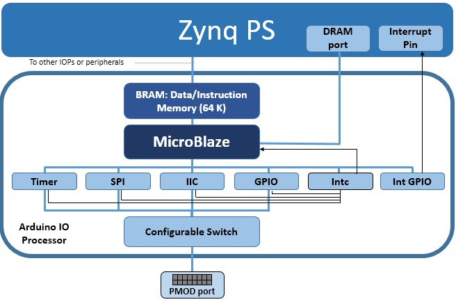
As indicated in the diagram, each Pmod PYNQ MicroBlaze has a MicroBlaze Subsystem a configurable switch, and the following AXI controllers:
AXI I2C
- SCL Frequency 100 KHz
- Address Mode: 7 bits
AXI SPI
- Master mode
- Transaction Width: 8
- SCK Frequency: 6.25 MHz
- FIFO Depth: 16
AXI GPIO
- 8 Input/Output pins
AXI Timer
- 32 bits
- 1 Generate Output
- 1 PWM Output
AXI Interrupt controller
Manages the interrupts of peripherals in the MicroBlaze subsystem.
Interrupt GPIO
- An additional AXI GPIO is used to signal interrupt requests to the PS
Configurable Switch
- Allows routing of signals from dedicated peripherals to the external interface.
A list of drivers provided for Pmod peripherals can be found in the pynq.lib.pmod Package section.
Examples
In the Base Overlay, two Pmod instances are available: PMODA and PMODB. After the overlay is loaded theses instances can be accessed as follows:
from pynq.overlays.base import BaseOverlay
from pynq.lib import Pmod_Timer

base = BaseOverlay("base.bit")

pt = Pmod_Timer(base.PMODA,0)
pt.stop()
More information about the Pmod subpackage, its components, and its API can be found in the pynq.lib.pmod Package section.
For more examples, see the notebooks in the following directory on the board:
<Jupyter Dashboard>/base/pmod/