PYNQ MicroBlaze Subsystem
The PYNQ MicroBlaze subsystem gives flexibility to support a wide range of hardware peripherals from Python. The PYNQ MicroBlaze is intended as an offload processor, and can deal with the low level communication protocols and data processing and provides data from a sensor that can be accessed from Python. The subsystem is deterministic, and is suitable for real-time control.
MicroBlaze applications will typically be developed in C or C++, and will run bare-metal.
The following sections show how to develop applications for the MicroBlaze soft processors running inside an overlay.
Memory Architecture
Each PYNQ MicroBlaze has local memory (implemented in Xilinx BRAMs) and a connection to the PS DDR memory.
The PYNQ MicroBlaze instruction and data memory is implemented in a dual port Block RAM, with one port connected to the PYNQ MicroBlaze, and the other to the ARM processor. This allows an executable binary file to be written from the ARM to the PYNQ MicroBlaze instruction memory. The PYNQ MicroBlaze can also be reset by the ARM, allowing the PYNQ MicroBlaze to start executing the new program.
The PYNQ MicroBlaze data memory, either in local memory, or in DDR memory, can be used as a mailbox for communication and data exchanges between the ARM processor and the PYNQ MicroBlaze.
DDR memory is managed by the Linux kernel running on the Cortex-A9s. Therefore,
the PYNQ MicroBlaze must first be allocated memory regions to access DRAM. The
PYNQ Xlnk() class is used to allocate memory in Linux. It also provides
the physical address of the memory. A PYNQ applications can send the physical
address to a PYNQ MicroBlaze, and the PYNQ MicroBlaze can then access the
buffer.
DDR Memory
The PYNQ MicroBlazes are connected to the DDR memory via the General Purpose AXI slave port. This is a direct connection, so it is only suitable for simple data transfers from the PYNQ MicroBlaze. The MicroBlaze can attempt to read or write the DDR as quickly as possible in a loop, but there is no support for bursts, or streaming data.
PYNQ MicroBlaze Memory Map
The local PYNQ MicroBlaze memory is 64KB of shared data and instruction memory. Instruction memory for the PYNQ MicroBlaze starts at address 0x0.
Pynq and the application running on the PYNQ MicroBlaze can write to anywhere in the shared memory space. You should be careful not to write to the instruction memory unintentionally as this will corrupt the running application.
When building the MicroBlaze project, the compiler will only ensure that allocated stack and heap of the application fit into the BRAM and DDR if used. For communication between the ARM and the MicroBlaze, a part of the shared memory space must also be reserved within the MicroBlaze address space.
There is no memory management in the PYNQ MicroBlaze. You must ensure the application, including stack and heap, do not overflow into the defined data area. Remember that declaring a stack and heap size only allocates space to the stack and heap. No boundary is created, so if sufficient space was not allocated, the stack and heap may overflow and corrupt your application.
If you need to modify the stack and heap for an application, the linker script
can be found in the <project_directory>/src/ directory.
It is recommended to follow the same convention for data communication between the two processors via a MAILBOX.
Instruction and data memory start 0x0 Instruction and data memory size 0xf000 Shared mailbox memory start 0xf000 Shared mailbox memory size 0x1000 Shared mailbox Command Address 0xfffc
These MAILBOX values for a PYNQ MicroBlaze application are defined here:
<PYNQ repository>/boards/ip/pmod_io_switch_1.0/drivers/    \
pmod_io_switch_v1_0/src/pmod.h
<PYNQ repository>/boards/ip/arduino_io_switch_1.0/drivers/ \
arduino_io_switch_v1_0/src/arduino.h
The corresponding Python constants are defined here:
<PYNQ repository>/pynq/lib/pmod/constants.py
<PYNQ repository>/pynq/lib/arduino/constants.py
The following example explains how Python could initiate a read from a peripheral connected to a PYNQ MicroBlaze.
- Python writes a read command (e.g. 0x3) to the mailbox command address (0xfffc).
- MicroBlaze application checks the command address, and reads and decodes the command.
- MicroBlaze performs a read from the peripheral and places the data at the mailbox base address (0xf000).
- MicroBlaze writes 0x0 to the mailbox command address (0xfffc) to confirm transaction is complete.
- Python checks the command address (0xfffc), and sees that the MicroBlaze has written 0x0, indicating the read is complete, and data is available.
- Python reads the data in the mailbox base address (0xf000), completing the read.
Running Code on Different MicroBlazes
The MicroBlaze local BRAM memory is mapped into the MicroBlaze address space, and also to the ARM address space. These address spaces are independent, so the local memory will be located at different addresses in each memory space. Some example mappings are shown below to highlight the address translation between MicroBlaze and ARM’s memory spaces.
| MicroBlaze Base Address | MicroBlaze Address Space | ARM Equivalent Address Space |
|---|---|---|
| 0x4000_0000 | 0x0000_0000 - 0x0000_ffff | 0x4000_0000 - 0x4000_ffff |
| 0x4200_0000 | 0x0000_0000 - 0x0000_ffff | 0x4200_0000 - 0x4200_ffff |
| 0x4400_0000 | 0x0000_0000 - 0x0000_ffff | 0x4400_0000 - 0x4400_ffff |
Note that each MicroBlaze has the same range for its address space. However, the location of the address space in the ARM memory map is different for each PYNQ MicroBlaze. As the MicroBlaze address space is the same for each Pynq MicroBlaze, any binary compiled for one PYNQ MicroBlaze will work on another PYNQ MicroBlaze.
For example, suppose a PYNQ MicroBlaze exists at 0x4000_0000, and a second
PYNQ MicroBlaze exists at 0x4200_0000. The same binary can run on the first
PYNQ MicroBlaze by writing the binary from python to the address space
0x4000_0000, and on the second PYNQ MicroBlaze by writing to
0x4200_0000.
Building Applications
There are a number of steps required before you can start writing your own software for a PYNQ MicroBlaze. This document will describe the PYNQ MicroBlaze architecture, and how to set up and build the required software projects to allow you to write your own application for the MicroBlaze inside an PYNQ MicroBlaze. Xilinx® SDK projects can be created manually using the SDK GUI, or software can be built using a Makefile flow.
MicroBlaze Processors
As described in the previous section, a PYNQ MicroBlaze can be used as a flexible controller for different types of external peripherals. The ARM® Cortex®-A9 is an application processor, which runs Pynq and Jupyter notebook on a Linux OS. This scenario is not well suited to real-time applications, which is a common requirement for an embedded systems. In the base overlay there are three PYNQ MicroBlazes. As well as acting as a flexible controller, a PYNQ MicroBlaze can be used as dedicated real-time controller.
PYNQ MicroBlazes can also be used standalone to offload some processing from the main processor. However, note that the MicroBlaze processor inside a Pynq MicroBlaze in the base overlay is running at 100 MHz, compared to the Dual-Core ARM Cortex-A9 running at 650 MHz. The clock speed, and different processor architectures and features should be taken into account when offloading pure application code. e.g. Vector processing on the ARM Cortex-A9 Neon processing unit will be much more efficient than running on the MicroBlaze. The MicroBlaze is most appropriate for low-level, background, or real-time applications.
Software Requirements
Xilinx SDK (Software Development Kit) contains the MicroBlaze cross-compiler which can be used to build software for the MicroBlaze inside a PYNQ MicroBlaze. SDK is available for free as part of the Xilinx Vivado WebPack.
The full source code for all supported PYNQ MicroBlaze peripherals is available from the project GitHub. Pynq ships with precompiled PYNQ MicroBlaze executables to support various peripherals (see PYNQ Libraries), so Xilinx software is only needed if you intend to modify existing code, or build your own PYNQ MicroBlaze applications/peripheral drivers.
The current Pynq release is built using Vivado and SDK 2016.1. it is recommended to use the same version to rebuild existing Vivado and SDK projects. If you only intend to build software, you will only need to install SDK. The full Vivado and SDK installation is only required to modify or design new overlays. Download Xilinx Vivado and SDK 2016.1 You can use the Vivado HLx Web Install Client and select SDK and/or Vivado during the installation.
Compiling Projects
Software executables run on the MicroBlaze inside a PYNQ MicroBlaze. Code for the MicroBlaze can be written in C or C++ and compiled using Xilinx SDK .
You can pull or clone the PYNQ repository, and all the driver source and
project files can be found in
<PYNQ repository>\pynq\lib\<driver_group_name>\<project_directory>,
(Where <PYNQ repository> is the location of the PYNQ repository).
SDK Application, Board Support Package, Hardware Platform
Each SDK application project requires a BSP project (Board Support Package), and a hardware platform project. The application project will include the user code (C/C++). The Application project is linked to a BSP. The BSP (Board Support Package) contains software libraries and drivers to support the underlying peripherals in the system.
Internally, the BSP is linked to a Hardware Platform. A Hardware Platform defines the peripherals in the PYNQ MicroBlaze subsystem, and the memory map of the system. It is used by the BSP to build software libraries to support the underlying hardware.
All Application projects can be compiled from the command line using makefiles, or imported into the SDK GUI.
You can also use existing projects as a starting point to create your own project.
Board Support Package
A Board Support Package (BSP) includes software libraries for peripherals in the system. For example, the SDK projects for Pmod and Arduino peripherals require the following 2 BSPs:
BSP for the Arduino PYNQ MicroBlaze:
<PYNQ repository>/pynq/lib/arduino/bsp_arduino/
BSP for the Pmod PYNQ MicroBlaze:
<PYNQ repository>/pynq/lib/pmod/bsp_pmod
A BSP is specific to a processor subsystem. There can be many BSPs associated with an overlay, depending on the types of processors available in the system.
An application for the Pmod PYNQ MicroBlaze will be linked to the Pmod Pynq MicroBlaze BSP. As the two Pmod PYNQ MicroBlazes are identical, an application written for one Pmod PYNQ MicroBlaze can run on the other Pmod PYNQ MicroBlaze.
An Arduino application will be linked to the Arduino PYNQ MicroBlaze BSP.
Building the Projects
To build all the software projects, for example, you can run the corresponding makefile:
<PYNQ repository>/pynq/lib/arduino/makefile
<PYNQ repository>/pynq/lib/pmod/makefile
Application projects for peripherals that ship with Pynq (e.g. Pmod and Arduino peripherals) can also be found in the same location. Each project is contained in a separate folder.
The makefile compiles the application projects based on the BSP provided in the correct location.
The makefile requires SDK to be installed, and can be run from Windows, or Linux.
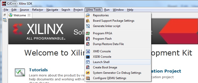
To run make from Windows, open SDK, and choose a temporary workspace (make
sure this path is external to the downloaded PYNQ repository). From the
Xilinx Tools menu, select Launch Shell.
In Linux, open a terminal, and source the SDK tools.
From either the Windows Shell, or the Linux terminal, navigate to the sdk folder in your local copy of the PYNQ repository:
The following example shows how to run make in
<PYNQ repository>/pynq/lib/pmod/:
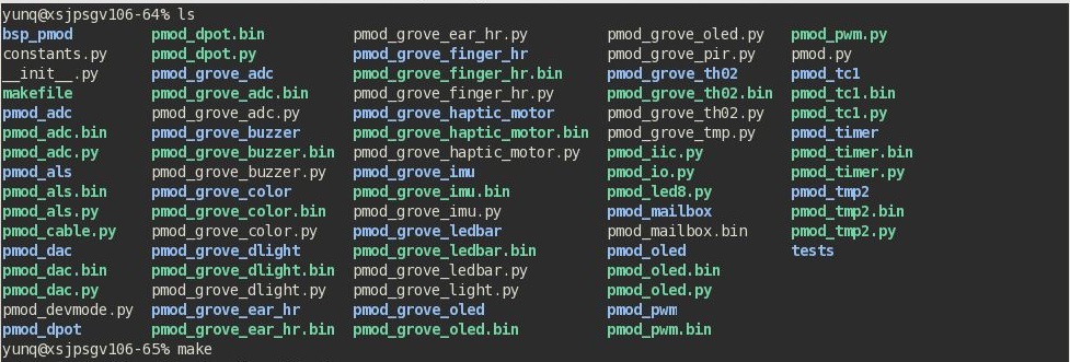
This will clean all the existing compiled binaries (bin files), and rebuild all the application projects.

If you examine the makefile, you can the BIN_PMOD variable at the top of the makefile includes all the bin files required by Pmod peripherals. If you want to add your own custom project to the build process, you need to add the project name to the BIN_PMOD variable, and save the project in the same location as the other application projects.
Similarly, you have to following the same steps to build Arduino application projects.
In addition, individual projects can be built by navigating to the
<project_directory>/Debug and running make.
Binary Files
Compiling code produces an executable file (.elf) which needs to be converted to binary format (.bin) to be downloaded to, and run on a PYNQ MicroBlaze.
A .bin file can be generated from a .elf by running the following command from the SDK shell:
mb-objcopy -O binary <input_file>.elf <output_file>.bin
This is done automatically by the makefile for the existing application
projects. The makefile will also copy all .bin files into the
<PYNQ repository>/pynq/lib/<driver_group_name>/ folder.
Creating Your Own
Using the makefile flow, you can use an existing project as a starting point for your own project.
Copy and rename the project, and modify or replace the .c file in the src/ with your C code. The generated .bin file will have the same base name as your C file.
For example, if your C code is my_peripheral.c, the generated .elf and .bin
will be my_peripheral.elf and my_peripheral.bin.
The naming convention recommended for peripheral applications is
<pmod|arduino>_<peripheral>.
You will need to update references from the old project name to your new
project name in <project_directory>/Debug/makefile and
<project_directory>/Debug/src/subdir.mk.
If you want your project to build in the main makefile, you should also append the .bin name of your project to the BIN_PMOD (or BIN_ARDUINO) variable at the top of the makefile.
If you are using the SDK GUI, you can import the Hardware Platform, BSP, and any application projects into your SDK workspace.
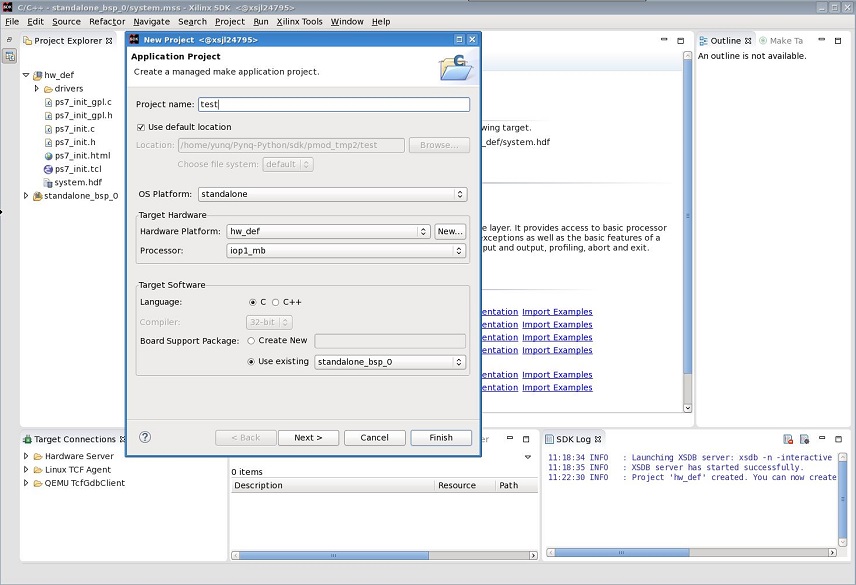
The SDK GUI can be used to build and debug your code.
Writing Applications
The previous section described the software architecture and the software build process. This section will cover how to write the PYNQ MicroBlaze application and also the corresponding Python interface.
The section assumes that the hardware platform and the BSPs have already been generated as detailed in the previous section.
Header Files and Libraries
A library is provided for the PYNQ MicroBlaze which includes an API for local peripherals (IIC, SPI, Timer, Uart, GPIO), the configurable switch, links to the peripheral addresses, and mappings for the mailbox used in the existing PYNQ MicroBlaze peripheral applications provided with Pynq. This library can be used to write custom PYNQ MicroBlaze applications.
The only IP that is specific to each PYNQ MicroBlaze is the configurable switch.
There is a pmod_io_switch and an arduino_io_switch. The header files
for the PYNQ MicroBlazes are associated with the corresponding configurable
switch, and can be found:
<PYNQ repository>/boards/ip/pmod_io_switch_1.0/drivers/    \
pmod_io_switch_v1_0/src/pmod.h
<PYNQ repository>/boards/ip/arduino_io_switch_1.0/drivers/ \
arduino_io_switch_v1_0/src/arduino.h
The corresponding C code, pmod.c or arduino.c can also be found in this
directory.
To use these files in a PYNQ MicroBlaze application, include these header file(s) in the C program.
For a Pmod PYNQ MicroBlaze:
#include "pmod.h"
#include "pmod_io_switch.h"
or for an Arduino PYNQ MicroBlaze:
#include "arduino.h"
#include "arduino_io_switch.h"
Pmod applications should call pmod_init() at the beginning of the
application, and Arduino applications, arduino_init(). This will initialize
all the PYNQ MicroBlaze peripherals in the subsystem.
Controlling the Pmod PYNQ MicroBlaze Switch
The PYNQ MicroBlaze switch needs to be configured by the PYNQ MicroBlaze
application before any peripherals can be used. This can be done statically
from within the application, or the application can allow Python to write a
switch configuration to shared memory, which can be used to configure the
switch. This functionality must be implemented by the user, but existing Pynq
MicroBlaze applications can be used as a guide. For example, the
arduino_lcd18 PYNQ MicroBlaze project shows and example of reading the
switch configuration from the mailbox, and using this to configure
the switch.
There are 8 data pins on a Pmod port, that can be connected to any of 16 internal peripheral pins (8x GPIO, 2x SPI, 4x IIC, 2x Timer). This means the configuration switch for the Pmod has 8 connections to make to the data pins.
Each pin can be configured by writing a 4 bit value to the corresponding place in the PYNQ MicroBlaze Switch configuration register. The first nibble (4-bits) configures the first pin, the second nibble the second pin and so on.
The following function, part of the provided pmod_io_switch_v1_0 driver
(pmod.h) can be used to configure the switch from a PYNQ MicroBlaze
application.
void config_pmod_switch(char pin0, char pin1, char pin2, char pin3, \
     char pin4, char pin5, char pin6, char pin7);
While each parameter is a “char” only the lower 4-bits are used to configure each pin.
Switch mappings used for PYNQ MicroBlaze Switch configuration:
| Pin | Value |
|---|---|
| GPIO_0 | 0x0 |
| GPIO_1 | 0x1 |
| GPIO_2 | 0x2 |
| GPIO_3 | 0x3 |
| GPIO_4 | 0x4 |
| GPIO_5 | 0x5 |
| GPIO_6 | 0x6 |
| GPIO_7 | 0x7 |
| SCL | 0x8 |
| SDA | 0x9 |
| SPICLK | 0xa |
| MISO | 0xb |
| MOSI | 0xc |
| SS | 0xd |
| PWM | 0xe |
| TIMER | 0xf |
For example:
config_pmod_switch(SS,MOSI,GPIO_2,SPICLK,GPIO_4,GPIO_5,GPIO_6,GPIO_7);
This would connect a SPI interface:
- Pin 0: SS
- Pin 1: MOSI
- Pin 2: GPIO_2
- Pin 3: SPICLK
- Pin 4: GPIO_4
- Pin 5: GPIO_5
- Pin 6: GPIO_6
- Pin 7: GPIO_7
Note that if two or more pins are connected to the same signal, the pins are OR’d together internally.
config_pmod_switch(GPIO_1,GPIO_1,GPIO_1,GPIO_1,GPIO_1,GPIO_1,GPIO_1,GPIO_1);
This is not recommended and should not be done unintentionally.
Controlling the Arduino PYNQ MicroBlaze Switch
Switch mappings used for IO switch configuration:
| Pin | A/D IO | A_INT | Interrupt | UART | PWM | Timer | SPI | IIC | Input-Capture |
|---|---|---|---|---|---|---|---|---|---|
| A0 | A_GPIO | A_INT | |||||||
| A1 | A_GPIO | A_INT | |||||||
| A2 | A_GPIO | A_INT | |||||||
| A3 | A_GPIO | A_INT | |||||||
| A4 | A_GPIO | A_INT | IIC | ||||||
| A5 | A_GPIO | A_INT | IIC | ||||||
| D0 | D_GPIO | D_INT | D_UART | ||||||
| D1 | D_GPIO | D_INT | D_UART | ||||||
| D2 | D_GPIO | D_INT | |||||||
| D3 | D_GPIO | D_INT | D_PWM0 | D_TIMER Timer0 | IC Timer0 | ||||
| D4 | D_GPIO | D_INT | D_TIMER Timer0_6 | ||||||
| D5 | D_GPIO | D_INT | D_PWM1 | D_TIMER Timer1 | IC Timer1 | ||||
| D6 | D_GPIO | D_INT | D_PWM2 | D_TIMER Timer2 | IC Timer2 | ||||
| D7 | D_GPIO | D_INT | |||||||
| D8 | D_GPIO | D_INT | D_TIMER Timer1_7 | Input Capture | |||||
| D9 | D_GPIO | D_INT | D_PWM3 | D_TIMER Timer3 | IC Timer3 | ||||
| D10 | D_GPIO | D_INT | D_PWM4 | D_TIMER Timer4 | D_SS | IC Timer4 | |||
| D11 | D_GPIO | D_INT | D_PWM5 | D_TIMER Timer5 | D_MOSI | IC Timer5 | |||
| D12 | D_GPIO | D_INT | D_MISO | ||||||
| D13 | D_GPIO | D_INT | D_SPICLK |
For example, to connect the UART to D0 and D1, write D_UART to the configuration register for D0 and D1.
config_arduino_switch(A_GPIO, A_GPIO, A_GPIO, A_GPIO, A_GPIO, A_GPIO,
              D_UART, D_UART, D_GPIO, D_GPIO, D_GPIO,
              D_GPIO, D_GPIO, D_GPIO, D_GPIO,
              D_GPIO, D_GPIO, D_GPIO, D_GPIO);
PYNQ MicroBlaze Example
MicroBlaze C Code
Taking Pmod ALS as an example PYNQ MicroBlaze driver (used to control the Pmod light sensor):
<PYNQ repository>/pynq/lib/pmod/pmod_als/src/pmod_als.c
First note that the pmod.h header file is included.
#include "pmod.h"
Some constants for commands are defined. These values can be chosen properly. The corresponding Python code will send the appropriate command values to control the PYNQ MicroBlaze application.
By convention, 0x0 is reserved for no command (idle, or acknowledged); then PYNQ MicroBlaze commands can be any non-zero value.
// MAILBOX_WRITE_CMD
#define READ_SINGLE_VALUE 0x3
#define READ_AND_LOG      0x7
// Log constants
#define LOG_BASE_ADDRESS (MAILBOX_DATA_PTR(4))
#define LOG_ITEM_SIZE sizeof(u32)
#define LOG_CAPACITY  (4000/LOG_ITEM_SIZE)
The ALS peripheral has as SPI interface. The user defined function get_sample()
calls an SPI function spi_transfer(), defined in pmod.h, to read data
from the device.
u32 get_sample(){
   /*
   ALS data is 8-bit in the middle of 16-bit stream.
   Two bytes need to be read, and data extracted.
   */
   u8 raw_data[2];
   spi_transfer(SPI_BASEADDR, 2, raw_data, NULL);
   return ( ((raw_data[1] & 0xf0) >> 4) + ((raw_data[0] & 0x0f) << 4) );
}
In main() notice config_pmod_switch() is called to initialize the
switch with a static configuration. This application does not allow the switch
configuration to be modified from Python. This means that if you want to use
this code with a different pin configuration, the C code must be modified and
recompiled.
int main(void)
{
   int cmd;
   u16 als_data;
   u32 delay;

   pmod_init(0,1);
   config_pmod_switch(SS, GPIO_1, MISO, SPICLK, \
                      GPIO_4, GPIO_5, GPIO_6, GPIO_7);
   // to initialize the device
   get_sample();
Next, the while(1) loop continually checks the MAILBOX_CMD_ADDR for a
non-zero command. Once a command is received from Python, the command is
decoded, and executed.
// Run application
while(1){

   // wait and store valid command
   while((MAILBOX_CMD_ADDR & 0x01)==0);
   cmd = MAILBOX_CMD_ADDR;
Taking the first case, reading a single value; get_sample() is called and a
value returned to the first position (0) of the MAILBOX_DATA.
MAILBOX_CMD_ADDR is reset to zero to acknowledge to the ARM processor that
the operation is complete and data is available in the mailbox.
Remaining code:
      switch(cmd){
         case READ_SINGLE_VALUE:
         // write out reading, reset mailbox
         MAILBOX_DATA(0) = get_sample();
         MAILBOX_CMD_ADDR = 0x0;
         break;
         case READ_AND_LOG:
         // initialize logging variables, reset cmd
         cb_init(&pmod_log, LOG_BASE_ADDRESS, LOG_CAPACITY, LOG_ITEM_SIZE);
         delay = MAILBOX_DATA(1);
         MAILBOX_CMD_ADDR = 0x0;

            do{
               als_data = get_sample();
               cb_push_back(&pmod_log, &als_data);
               delay_ms(delay);
            } while((MAILBOX_CMD_ADDR & 0x1)== 0);

            break;

         default:
            // reset command
            MAILBOX_CMD_ADDR = 0x0;
            break;
      }
   }
   return(0);
}
Python Code
With the PYNQ MicroBlaze Driver written, the Python class can be built to communicate with that PYNQ MicroBlaze.
<PYNQ repository>/pynq/lib/pmod/pmod_als.py
First the Pmod package is imported:
from . import Pmod
Then some other constants are defined:
PMOD_ALS_PROGRAM = "pmod_als.bin"
PMOD_ALS_LOG_START = MAILBOX_OFFSET+16
PMOD_ALS_LOG_END = PMOD_ALS_LOG_START+(1000*4)
RESET = 0x1
READ_SINGLE_VALUE = 0x3
READ_AND_LOG = 0x7
The MicroBlaze binary file for the PYNQ MicroBlaze is defined. This is the application executable, and will be loaded into the PYNQ MicroBlaze instruction memory.
The ALS class and an initialization method are defined:
class Pmod_ALS(object):

   def __init__(self, mb_info):
The initialization function for the module requires the MicroBlaze information.
The __init__ is called when a module is initialized. For example,
from Python:
from pynq.lib.pmod import Pmod_ALS
from pynq.lib.pmod import PMODA
als = Pmod_ALS(PMODA)
This will create a Pmod_ALS instance, and load the MicroBlaze executable
(PMOD_ALS_PROGRAM) into the instruction memory of the specified Pynq
MicroBlaze.
Since the MicroBlaze information, imported as Pmod constants, can also be extracted as an attribute of the overlay, the following code also works:
from pynq.overlays.base import BaseOverlay
base = BaseOverlay("base.bit")
als = Pmod_ALS(base.PMODA)
In the initialization method, an instance of the Pmod class is
created. This Pmod class controls the basic functionalities of the
MicroBlaze processor, including reading commands/data, and writting
commands/data.
Internally, when the Pmod class is initialized, the run() call pulls
the PYNQ MicroBlaze out of reset. After this, the PYNQ MicroBlaze will be
running the pmod_als.bin executable.
The read() method in the Pmod_ALS class will read an ALS sample and
return that value to the caller. The following steps demonstrate a Python to
MicroBlaze read transaction specific to the Pmod_ALS class.
def read(self):
First, the command is written to the MicroBlaze shared memory. In this case
the value READ_SINGLE_VALUE represents a command value. This value
is user defined in the Python code, and must match the value the C program
expects for the same function.
self.microblaze.write_blocking_command(READ_SINGLE_VALUE)
The command is blocking so that Python code will not proceed unless an
acknowledgement has been received from the MicroBlaze. Internally, after the
PYNQ MicroBlaze has finished its task, it will write 0x0 to clear the
command area. The Python code checks this command area (in this case, the Python code
constantly checks whether the 0x3 value is still present at the
CMD_OFFSET).
Once the command is no longer 0x3 (the acknowledge has been received), the
result is read from the data area of the shared memory MAILBOX_OFFSET.
data = self.microblaze.read_mailbox(0)
return data