MicroBlaze Subsystem
The PYNQ MicroBlaze subsystem can be controlled by the PynqMicroblaze class. This allows loading of programs from Python, controlling executing by triggering the processor reset signal, reading and writing to shared data memory, and managing interrupts received from the subsystem.
Each PYNQ MicroBlaze subsystem is contained within an IO Processor (IOP). An IOP defines a set of communication and behavioral controllers that are controlled by Python. There are currently three IOPs provided with PYNQ: Arduino, PMOD, and Logictools.
Block Diagram
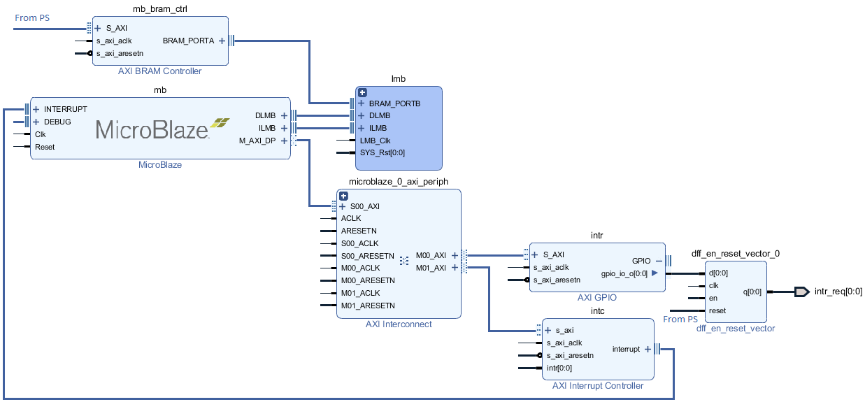
A PYNQ MicroBlaze subsystem consists of a MicroBlaze processor, AXI interconnect, Interrupt controller, an Interrupt Requester, and External System Interface, and Block RAM and memory controllers.
The AXI interconnect connects the MicroBlaze to the interrupt controller, interrupt requester, and external interface.
- The Interrupt Controller is the interface for other communication or behavioral controllers connected to the MicroBlaze Processor.
- The Interrupt Requester sends interrupt requests to the Zynq Processing System.
- The External Interface allows the MicroBlaze subsystem to communicate with other communication, behavioral controllers, or DDR Memory.
- The Block RAM holds MicroBlaze Instructions and Data.
The Block RAM is dual-ported: One port connected to the MicroBlaze Instruction and Data ports; The other port is connected to the ARM® Cortex®-A9 processor for communication.
If the External Interface is connected to DDR Memory, DDR can be used to transfer large data segments between the PS (Python) and the Subsystem.
Examples
In the Base Overlay, three IOP instances with PYNQ Microblaze Subsystems are available: iop1 (PMODA), iop2 (PMODB), and iop3 (Arduino). After the overlay is loaded these can be accessed as follows:
from pynq.overlays.base import BaseOverlay
from pynq.lib import PynqMicroblaze

base = BaseOverlay('base.bit')

mb = PynqMicroblaze(base.iop1.mb_info,
                    "/home/xilinx/pynq/lib/pmod/pmod_timer.bin")
mb.reset()
More information about the PynqMicroblaze class, and its API can be found in the pynq.lib.pynqmicroblaze.pynqmicroblaze Module section.
Pmod, Arduino, and Grove classes are subclasses of the PynqMicroBlaze class, and further example notebooks can be found in those sections.
Creating a New PYNQ Microblaze
Any hierarchy that contains a Microblaze and meets the above requirements of having AXI-accessible code memory, a PS interrupt line and a reset line can be used in PYNQ. However in order to use your Microblaze with the IPython magic you must provide a board support package (BSP). BSPs are generated from Xilinx SDK and contain all of the drivers and configuration data for the peripherals attached to the Microblaze.
PYNQ provides a TCL script to generate the BSP from the hardware description
file which can be found in the boards/sw_repo directory of the repository,
along with the drivers needed for Python/C communication and the pynqmb
hardware abstraction library. Creating and using the BSP requires the following
steps:
- Export Hardware from Vivado to generate the HDF file
- In the
boards/sw_repodirectory runmake HDF=$HDF_FILE. If no HDF is provided then the Base Overlay BSPs will be generated. - Copy the generated BSP on to the board and ensure it is name
bsp_${hierarchy}where${hierarchy}is the name of the Microblaze hierarchy in your design. If you have multiple Microblazes it can all be a prefix common to all hierarchies. - Call
add_bsp(BSP_DIR)in Python. This can be done as part of initialisation of your overlay.
These steps will integrate the BSP into the PYNQ runtime and allow the IPython
%%microblaze magic to be used with the new Microblaze subsystem.
If you wish to reuse an existing subsystem, as long as it is named in
accordance with the Base Overlay - e.g. iop_pmod* or iop_arduino* then
the correct BSP will be used automatically.